Full Wave Controlled Rectifier Circuit Diagram
Single-phase, full-wave,controlled rectifier (electric motor) With the help of neat circuit diagram explain the working of half and Rectifier explain cycle
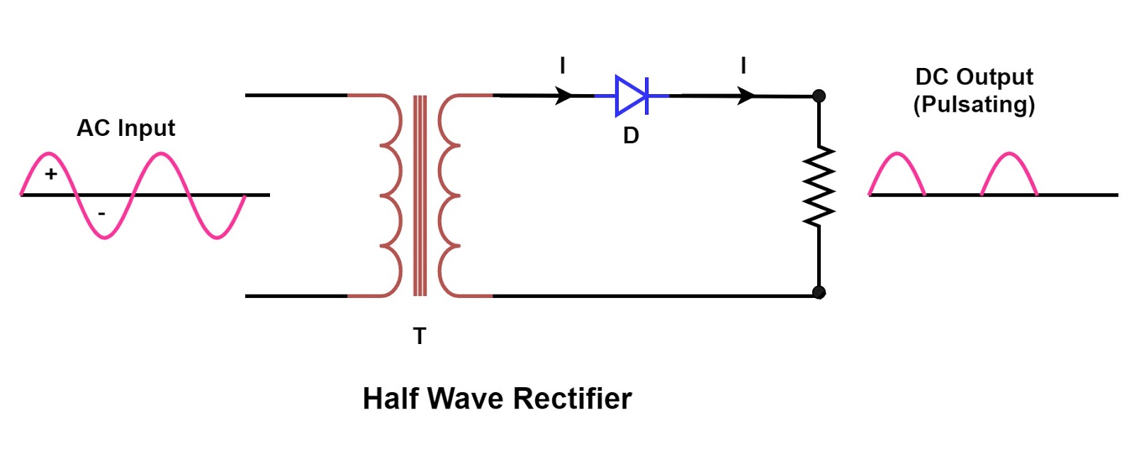
With the help of neat circuit diagram explain the working of half and
Principle of phase control (single phase half wave controlled rectifier Single phase half wave rectifier- circuit diagram,theory & applications Phase rectifier controlled rl inductive circuit highly principle operation loads
Rectifier transformer tapped output waveform input
Rectifier phase single full controlled wave motor electric mode discontinuous figureRectifier circuit diagram Rectifier circuitstoday tapped waveform multisim simulation repixFull wave rectifier circuit diagram in multisim.
.


Single Phase Half Wave Rectifier- Circuit Diagram,Theory & Applications

With the help of neat circuit diagram explain the working of half and

Full Wave Rectifier Circuit Diagram In Multisim - Grundlagen Http Sites

Principle of Phase Control (Single Phase half wave Controlled Rectifier

Rectifier Circuit Diagram | Half Wave, Full Wave, Bridge - ETechnoG